Comprehensive Review of K R Models 4mm scale 4DD

|
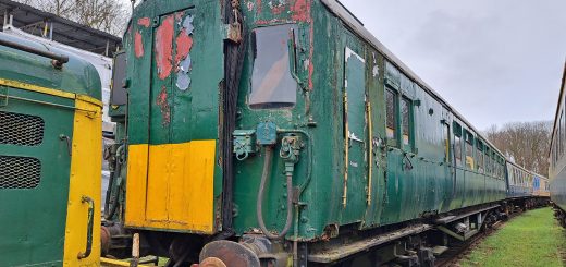
Introduction: I ordered my two 4DD models from KR Models on 24th March 2022, within 30 minutes of receiving the e mail announcing these new models. They were finally delivered on the 19th November 2025. So has the wait been worth it? Well in my biased opinion, although extended waits are not welcome, any new model of a Southern Electric unit is very welcome. However, having thoroughly appraised the model, perhaps the question ought to be “has the model been worth the wait?” Read on and make your mind up….. I ordered two. The BR green with small yellow warning panel version (which whilst not specified at the time of ordering comes with the odd white surround to the headcode windows, applied at Eastleigh during a re-paint, that it carried for a mercifully only a short while) and a BR blue version. If modelling the Southern Electric system is a small niche of modelling, then producing a model of a class that only had two four car units, that only ran on a small number of routes, and mostly ran during the morning and evening peaks, is a micro-niche. It can be viewed as a courageous decision to produce as a model, but on the other hand the 4DDs have the cachet of being the only double deck train ever to run in Britain so far. (At this point an uber-pedant will point out that whilst always known as a double deck train arguably it is a bi-level as the compartments are interlaced, not stacked!) There is usually a market for models of unique or special trains. Reference materials I have consulted for this appraisal are:
|
 A pair of cab fronts, both later versions. Note the obvious absence of the windscreen wipers. |
|
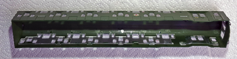
Packaging: We get off to a good start. The four coaches come protectively wrapped in polythene, placed in cut-outs in fairly dense foam within a shallow rectangular stout cardboard box, wrapped in a sealed disposable polythene wrap. None of the wasteful nonsense of a stout cardboard box about nine times the volume of the model, the box also coming in an outer clear plastic sleeve, and the model within is wrapped in polythene contained within a clear plastic crate within a clear plastic sleeve, surrounded by deep foam within the box. And despite this protection small parts still become detached during transit! No parts from my two units were detached during transit and with the foam being sufficiently flexible it was easy to extricate the coaches without damage. The only parts separately supplied to be fitted by the modeller are pair of dummy screw couplings and sheet of headcodes. Also supplied is an impressive 12 page A4 size booklet which contains an illustrated history of the 4DDs written by John Atkinson, information about preservation of the two remaining 4DD vehicles, and instructions for the model. However, right from the start doubts about poor attention to detail by K R Models are raised. The booklet (with 2 exceptions) insists on calling the 4DDs’ designer as Oliver Bullied (sic). Perhaps they can blame a spelling checker for this, but then you can usually add spellings to a custom dictionary, and ultimately such multiple mistakes ought to have been noticed and corrected. Not a perfect start then. The body: The 4DD consists of two DMBS vehicles and two TS vehicles. So only two sets of tooling are required for the four car unit. The bodies are single piece injection moulded shells with single piece flush gazing inserts. The only separately applied parts are the multiple unit jumper cables, mu conduits and mu receptacles on the cab fronts, driver’s cabs and guard’s compartments roof ventilators, the airhorns (when fitted – I do not know about the earlier whistles) and the long grab rails to the driver’s cabs and guard’s compartments. The quality of the moulding is generally very good. For instance the sharpness and size of the conduits on the roofs and on inner ends, and vertical strengthening ribs on the inner ends, are every bit as good as on Hornby and Bachmann Southern units. However, the representation of the lamp brackets on the cab fronts and all door handles (the 4DDs did not have commode handles) are of the standard of moulded detail on a 1970s’ era Lima class 33. |
 Interior of the body shell of a DMBS showing the flush glazing unit. |
|
The shape of the bodies is very good. The 4DDs have a flat body side, but with a very slight taper to the top (quoted as 1 inch taper in at the cornice), and this is credibly reproduced. Try putting a straight edge from floor to roof to notice this subtlety – even if not to precise sub-millimetre measurements. The curvature of the roof, when offered up to the Mike King drawing, does not quite match as the drawing has a slightly flatter curve, however the model looks more like in the photos, so I’ll give it benefit of the doubt. The layout of the windows and doors is accurate. Major dimensions – length over bodies and length from front buffers to inner ends (DMBS cars), car width, car height, length between bogie centres, powered and unpowered bogie wheelbases, and the diameter of all wheels – are completely accurate. Widths and heights of the doors are correct. I did not check every single axle on both units, but wheel back-to-back measurements, where measured, were correct. Though some were very close to being under gauge. However, according to Mike King’s drawings all windows on this model are consistently a fraction too small, approaching 1mm too narrow and too short. I did not notice this just looking at the model, excepting the windows to the upper compartments which consequently do not appear to go high enough into the roof. Some modellers have expressed an opinion, which occurred to me as well, that we look down on a model whereas the prototype is usually viewed from platform and ground level, so the model will look different. Indeed, photos I took of my model from “ground level” looked better than those taken from an elevated position. Southern Electrics Volume 2 1948-1972/Kevin Derrick/Strathwood, specifically pages 32 and 33, has large clear pictures of the roofs of 4001 and 4002. Comparing these pictures to the model indeed suggests that the model’s windows do not go quite high enough into the roof. I measured the height of the upper compartment windows on the 2D drawing and then cut a piece of paper to this length, offering it up to the model’s window and wrapping it around the curve. The tops of these windows were found to be about 1mm too low. I also think the prismatic effect of the flush glazing is particularly noticeable on a curved window and it does not help it look right. The positions of the rain strips were also measured by the same method and also found to be about 1mm too low. |
 Roof details on a DMBS. |
|
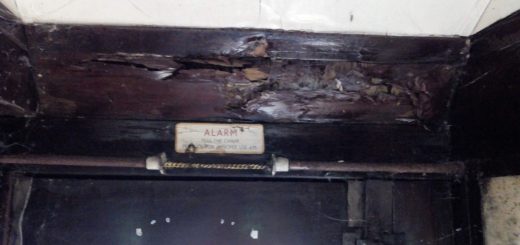
The rounded rectangular vents to the upper compartments on the model are 16mm long but should only be about 8mm long. This over-length is extremely obvious. There are no periscopes on my two models. This is probably accurate for their period, but I have been unable to find a picture of 4002’s DMBS roof in its green sywp era to confirm the accuracy of this version. Mike King’s drawings for the roof details are annotated as “typical roof conduit layouts”, so maybe not totally accurate. The drawings are significantly different to the model. The roof photos in Southern Electrics Volume 2 1948-1972 are again helpful here. The details of both DMBS and TS are clear enough to judge that Mike King’s drawings, whilst not totally accurate, are more accurate than the model. I will not go into detail about the specific inaccuracies in the number of conduits and their layouts, suffice it to say that the model is significantly different to photographs in places. Some roof photos show there to be a fourth circular vent above the guard’s compartments, lower down the roof, not along the centre line as the other three. However other photos show the roofs without. I suspect that at some time towards the end of the units’ lives they were removed, but according to pictures later than when the periscopes were removed. Neither of my two models have these lower vents. <This paragraph has been revised from the original version> The coaches are coupled together with electrically conducting couplings which are handed. The handed couplings unfortunately result in the wrong ends of the trailers being coupled to the power cars. Mike King’s drawings call the cabs end “A”, inner ends to the DMBS and one end of each TS “B” and the other inner ends of the TS cars “C”. The correct unit formation is A-B + B-C + C-B + B-A. However, the model, as produced, is A-B + C-B + B-C + B-A. Initially I thought the trailers may have been assembled incorrectly? However, it was then something I had missed was pointed out to me, namely that one end of the chassis of each trailer has a footstep and continuation of a conduit moulded onto it, which align with the coach end above. The following has been tried successfully and the trailer bodies can easily be reversed on their chassis, however, the moulded detail on the chassis ends will have to be removed and replaced with a step and conduit made of Plastikard and wire respectively on the other ends. The bodies are easy to remove (follow instructions in the booklet) and replace, just be careful to avoid damaging detail on the underframe whilst handling. |
 “B” end. Note the female multi pin coupling. |
 “C” end. Note the male multi pin coupling and central buffer. |
|
Details on the inner ends are different to those on Mike King’s Drawings. As with the roof conduits I am not listing specific differences, the overview being the B end only has minor discrepancies but the C ends are significantly different, particularly in respect of two equipment boxes not being portrayed. Unfortunately, I have yet to find any pictures of the inner ends to confirm the reality. The cab ends are modelled without windscreen wipers, which is rather obvious. It makes the models’ cab ends look like pictures I have of the DMBS at Sellindge during storage and restoration! Paint is very well applied and the printing of numbers and lettering razor sharp. Every bit as good as on Hornby and Bachmann models. Finish is a matter of personal opinion, but I am happy with the satin finish. The perception of colour is complex and differs between individuals, the production and reproduction of colour is subject to a number of physical factors. If you have read any of my previous reviews you will know I never declare a colour correct or incorrect, merely credible or not. I think the BR blue finish is credible. However, I am not at all happy with the shade of green, which I do not consider credible. It is a pleasing shade of green and would look credible on a model of series 1 & 2 Land Rovers, as I think it is in the region of mid-bronze green. Even allowing for any scale compression of colour it does not match any shade of green used by the Southern Region when compared to HMRS colour-controlled colour swatches. It is definitely not BR Green No.11, which it should be after 1956, nor is it the earlier post nationalisation “version” of Southern malachite (this is how it is described in various accounts) applied to all regions’ multiple units until 1956. One thing I immediately noticed when I unwrapped the coaches, and subsequently on publicity photos of the versions I do not have, is that coach numbers on both DMBS and TS cars of both units are not always in the correct quantity or positions, and on the green unit car numbers are white, not yellow. Each side of the DMBS cars has coach numbers at each end, so four in total. The TS cars have the correct quantity of car numbers but on either side at the same end. I cannot find photographic evidence nor documentation to support any of this. These are pretty gross errors given that the positions and colours of BR coach numbering are well documented and photographed. |
 |
 |
| above: Both sides of the same TS (note the couplings are different), showing that the coach number on one side is incorrectly on the left. In other words, both coach numbers are at the same end. |
 An interesting photo of DMBS S13004S taken by Mike Radford at Sellindge about 15 years ago. This is right hand end of the nearside and having removed paint carefully shows that white coach numbers were applied at two positions at different times and the upper white numbers were applied not quite in register over the previous yellow numbers. It also demonstrates that the shade of green used on the model is not correct. |
|
Some of the compartment windows have the recognisable red no smoking triangle markings, not always added to RTR coaches, so well done K R Models for this. The ratio of smoking to not no smoking accommodation changed over time so reference to the Appendices of the Carriage Working Notices of the time appropriate to each version will be required to establish veracity. My two models had the same amount of no smoking accommodation and in the same compartments. However, the triangular markings fill the entire width of the inset of the flush glazing. This is probably a combination of the markings being too large and the windows too narrow. Also the no smoking triangles have only been put onto one window on each side of the compartment whereas I recall on, say a 4Sub unit, they appeared either side of the door on both sides of the coach. Finally for this section, as delivered some bodies were not fully pushed home and engaged to lugs on the chassis.
Interiors and Lighting: The interiors are injection moulded in shiny buff plastic and are rather basic – reminiscent of Triang-Hornby Mk1 coaches in the 1960s. They can be fairly clearly seen through the numerous windows and I think they would be better off moulded in, say, a mid-grey to reflect Trojan moquette. Of course the modeller can add details themselves. Maybe add seated and standing passengers expiring with bright pink faces (if representing the summer) or mist the window interiors for condensation (if representing the winter)!
|
 4DD accommodation shown in the Appendix to Carriage Working Notices June 1952. Note it also includes “Ladies Only” compartments, which as a child of the 1950s I recall that children were also permitted within. The wife of a fellow Southern railway and modelling enthusiast, who used to travel on these trains, describes them as being a “Mecca for bum pinchers and breast squeezers”, so 4 Ladies compartments may have been insufficient! |
 Interior and chassis of a DMBS. |
|
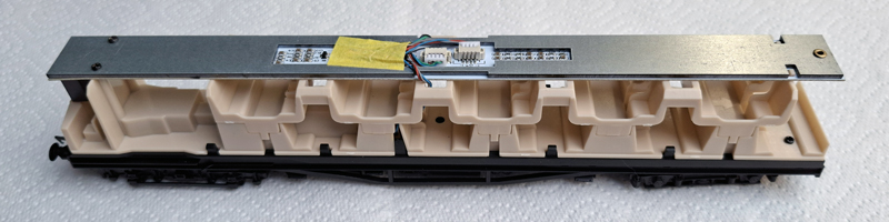
Atop the interior moulding is a LED lighting bar, from which lighted headcode boxes are attached underneath at the driving cab ends of the DMBS interiors. Unlike on Bachmann Southern EMUs heacode illumination is not red on the rear cab. Good! I prefer the rear headcode to be white and to rely on red blank blinds so you do not get a numerical headcode incorrectly illuminated red in one direction. When using DCC the headcode, cab and compartment lights can be separately switched. The instructions incorrectly call the headcode a number plate. Uniquely the cab lights are directional and light when the train is stopped on DCC. Unlike on other manufacturers multiple units there are no DIP switches to control lighting when using DC. In my opinion the compartment lighting is too bright, showing up the basic interior, and a tad too white for its era. Headcode box lighting is also perhaps a bit too white but I have not yet applied the headcode stickers. The instructions do not mention applying these stickers. I assume they are intended to be applied on the outside of the headcode window, as on Hornby Southern EMUs, but I have never liked the look of this as the headcode blinds they are representing are actually behind glass. However, with the headcode boxes being attached to the lighting bar I am wondering if the stickers can be applied to the front of the box and thus appear behind the headcode window. I will experiment with this when I get more time. Headcodes supplied are 55, 66, 75, 76 & 86, but unfortunately there are no white and red blanks, which is a shame. These headcodes are correct for Charing Cross or Cannon Street to Gravesend routes around the lifetime of these trains. Chassis, Bogies Underframe and Drive Mechanism: The chassis are heavy and I think they may be metal. A magnet indicates they are certainly not Iron based, so are probably a Zinc based alloy. Plastic details are attached which are not as refined as on other manufacturers’ models. They sufficiently match drawings and photos though. Like the real trains there are powered motor bogies under the cabs at each end. However, only one DCC decoder is required, of which more later. Excellent! There is a small motor and flywheel driving both axles of the motor bogie via a drive shaft and short gear tower. This assembly is placed under a raised floor in the guards’ compartment and under the first upper compartment, so is not visible. Very good! |
 The drive mechanism and motor bogie on a DMBS. |
|
Remarkably, and commendably, there is all-wheel pickup on all four cars. This is an amazing 32 wheel pickup! These feed a track power busbar into the DCC decoder socket. The DCC decoder socket then feeds power to both motors via motor power busbars. This means that one DMBS (the odd numbered power car) can run alone as, in effect, a locomotive, but the other (even numbered) power car needs to be coupled to the first, either directly or via the trailers, to run. This is all good stuff! The unit is coupled together using 8 pin electrically conducting handed couplers which push together and take apart easier than most. Hurrah! These require pushing fully home to a quiet “click”. There are guides to assist pushing couplers together and the underside of these guides have corresponding circular lugs and circular notches. These look like they are for locking the two couplers together, except when fully pushed home the lugs and notches do not meet! I have noticed that despite pushing the couplers fully home there is a tendency to slightly pull apart when running, but so far, with very limited running (read later), not enough to lose electrical continuity or completely uncouple. The power busbars account for four of the eight wires along the cars, the other four wires I suspect somehow control the three lighting circuits and connect loudspeakers in both power cars in parallel. Out of the box I found one of my even numbered power cars (the green version) was electrically dead despite remaking the couplings between all cars several times. I took the body off and had a peek at the mechanism and electrics, but could not see anything wrong. To test I wanted to try powering the motor directly, but could not get to the motor terminals without taking it more apart and removing wiring insulation. For the want of something to do I remade the two 4pin JST plug connections on the upper circuit board, not expecting it to make any difference. But after I put the body back on and coupled it to the other power car it sprung into life! The bogies on this model are modelled to OO gauge, not 4mm scale, width. So, the shoe beams align with conductor rail on 16.5mm gauge track (but without contacting correct height conductor rail), unlike the vast majority of other Southern Electric models where they are positioned outside of the conductor rail. This will make converting them to EM or S4 difficult. Stepboards (where fitted on the prototype) on unpowered bogies are not reproduced at all. As on the real trains between cars there are single centrally placed buffers on the end of one car buffering to a rubbing plate on the adjacent car. The modelled central buffers between cars are sprung. However, despite in reality, and on a diagram in the instructions, there is no central buffer between the two trailer cars, only between the driving cars and trailers. The weight of power cars is approximately 270g and trailers approximately 250g, one would think good for traction and staying on the track. |
 Underframe of a DMBS, the motor bogie being on the right. |
 Underframe of a TS. Note handed couplings on each end and the guide mechanism on the underside of the male coupling on the right. |
 Another interesting photograph of DMBS S13004S taken by Mike Radford at Sellindge about 15 years ago shows that at some stage it has gained a conventional pair of buffers on its inner end. Whether this was during its BR service or a modification after preservation (to be able to run with other coaches or a locomotive?) is not known. |
|
Running the model: I would love to be able to report that my two units ran smoothly and powerfully. Conspicuously neither can run around my layout for more than a few train lengths without derailing. This happens on plain straight track as well as on curves and on points. My layout has Peco Code 75 Bullhead track with large radius points and the mainline I used for testing has a minimum radius curves of 914 mm (3 feet in old money!) with compensation. I do not often get derailments on my track, so a derailment every few train lengths is rather extreme. I did some systematic tests. A single vehicle, whether self-powered, or a trailer pushed along by hand, runs freely and well without derailments. Couple two cars together, whether as a 2DD, or power car plus trailer, or two trailers together, and the regular derailments happen, invariably to one or several of the inner bogies. Lengthen the formation and it gets worse. The close coupling mechanism does not appear to open up properly on curves, though this was tested on my comparatively generous radius curves. <This paragraph has been revised from the original version> Such derailments have happened before. Like when Bachmann introduced their new Mk1s with close coupling mechanism. This mechanism’s swing arm had a small moulding pip that was rubbing on the centreing spring, causing resistance and binding, thus causing adverse lateral “vector forces”. To cast my degree in Physics aside, basically – tug a coach at an angle away from the direction of travel and it will try to tug it off the track! For any coupling to work reliably it has to be able to transfer the force completely in a straight line between the couplers’ pivot points, which are on a close coupling mechanism are moveable. The solution with the Bachman Mk1s was to take the mechanism apart to file off the pip, but I found just removing the spring worked just as well and requires no disassembly. Other similar close coupling mechanisms – like the Keen system – do not have the springs and in my limited experience work well. A fellow modeller has removed the springs and found it has ameliorated the derailment issue. Another modeller has found that as manufactured the close coupling mechanism has no vertical flexibility, which can also lead to derailing, especially if your layout has gradients. He has a successful solution, which involves more work, but which can be done whilst reversing the trailer bodies, though all four cars will need treatment. Please see the appendix at the end of this review. Additionally the bogies on the 4DD can touch the swing arm of the mechanism when pivoting, particularly on tighter radii. The bogies do not rotate particularly freely and the cars are so close coupled that the central buffers, where fitted, are actually buffing. None of this can help as they will contribute adverse vector forces. I have not yet had time to experiment with potential remedies, but lubricating the close coupling mechanisms will be a good start, and then look at the bogie cross-frame member touching the swing arm (perhaps remove it?), followed by preventing the central buffers causing friction. Note all these problems occur on both of my models. So it is more than a single rogue model. Because of the regular derailments I have so far been unable to assess how powerful this model is. Can it, as I have seen in a You Tube video, haul a trailing load (like an unpowered 4DD made from a kit)? My layout is level so I have also been unable to assess how it copes with gradients. |
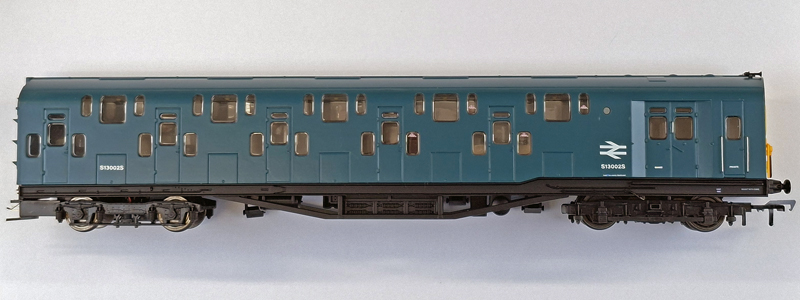 The offside/resistor grid side of the blue DMBS. Note the erroneous coach number on the left end of the car. |
|
Conclusion: I am frustrated by these models. They are a right old “curate’s egg! There are some very good aspects which deserve praise, but there are a lot of negative aspects. As a model in isolation, albeit with a few poorly moulded details and the absence of windscreen wipers, they look impressive enough. But when comparing them to the prototype, and running them, the good impression is reversed. I never go looking for problems. I would far rather find a new and expensive model well-built and accurate. A significant number of discrepancies were noticed on just causal looking, even when still in the box, and when looking closer, comparing to drawings and photos, errors and omissions just kept coming and coming. Then there is the inability to stay on the rails. I have assisted with researching and developing Southern Electric RTR models so I do not underestimate the challenges of the task. There are an enormous number of dimensions and details to verify and numerous issues to resolve, then there is the need to reproduce them as accurately as possible in a small scale. Compromises are required, not only for financial viability reasons but also because of the properties of materials used. Then there is the poor to non-existent version control of drawings when working with factories in China. During the iterative process changes made in previous drawings can become undone, meaning every detail needs to be checked and rechecked meticulously. Ironically photos and drawings in the supplied booklet clearly illustrate inaccuracies on the model, you do not need to spend months researching in obscure libraries. My reference sources came straight off my bookshelf. It should not cost more, and take longer, to get well documented and photographed details correct. I know the occasional mistake can slip through, no matter how careful you are, but the conclusion that these models suffer from poor attention to detail is inescapable. The result is that even with using modern design tools, modern materials, and modern production processes, unfortunately this is a model with the overall fidelity to the prototype train of a model designed and produced 30 years earlier. Also its propensity to derail is not good. Other manufacturers can produce more accurate and better running models for the same price. One should not have to do so much work to correct a model. Some modellers have expressed an opinion that any RTR 4DD model is better than none, but I think in 2025 we deserve better. Sadly, this could have been a definitive model, so what a missed opportunity! Colin Duff. Modelling Officer. 7th December 2025 |
 Comparison of cab sides of blue and later green versions. |
| Appendix: SOLUTION TO THIS MODEL DERAILING ON CURVES AND GRADIENTS By Dave Langton Is it the track or the train? Out of over 800 motorised units in my collection, comprising of steam, electrics, diesels and railcars from all the UK manufacturers, plus most of the big continental brands, I have to say the KR Models 4-DD is by far the most flawed design mechanically and consequently the most difficult to get running smoothly. The problem The problem lies in the couplings which carry eight separate electrical connections via a plug and socket with no vertical compliance whatsoever. Other models such as the EFE/Realtrack class 143/144, Hornby 4-VEP and the Bachmann class 117 have a similar arrangement but they incorporate a significant degree of vertical play to provide trouble-free running. A good test is to place any train on level, straight track and then lift one bogie by 1 or 2mm as if to represent an undulation in the track, which you would expect to find on any layout with gradients or slight imperfections. Indeed real railway lines will probably undulate by this amount. Doing this on any train, whether it has simple tension lock couplings or multi-pin plugs, should not lift the adjacent coach or bogie. If it does, then it’s doomed to derail. Now take your 4-DD and perform the same test. You will find there is no allowance whatsoever; the couplings are completely rigid in the vertical plane. What’s the solution? You could complain, send it back or hope KR models offer a fix. If you’re a serious modeller who relishes the challenge of kitbuilding, scratchbuilding or modifying models then you may decide that solving the problem is a fascinating and rewarding part of this diverse hobby. Begin by removing the body. Fortunately, that’s very simple as it’s just a clip fit. Next, remove the lighting bar and seating unit to reveal the metal weight. It may be worth unplugging the lighting bar to prevent damage to the delicate wiring. We’re aiming to give the close coupling mechanism more space to move up and down and this is achieved by loosening the metal weight; there’s a screw at each end. You will now discover the coupling can tilt down by about 1mm which is a good start. Unfortunately, the loose weight will simply bear down on the coupling so the solution to this is to insert a shim of plasticard under the weight to raise it up slightly. The thickness is rather critical because if it’s too thick, the body will no longer clip back on. I found that between 0.5 and 0.6mm plasticard worked best. You could add a whole sheet of plasticard the length of the coach but I decided just to add four small triangles at each corner of the coach, and another couple of transverse strips along the length of the coach to stop the solebar distorting when the weight is screwed back in. I thought that may be sufficient and it was an easy fix but I was wrong. The couplings are now free to tilt downwards but they’re so close to the headstocks that they will still not tilt upwards. This means your 4-DD would now be fine over the brow of the Lickey incline (yes I know – there’s no 3rd rail!) but it will still derail at the bottom of the incline. Lowering the coupling looks to be impossible and there’s very little to shave off the top of the plug so the only viable solution is to trim the bottom of the headstocks. Not wanting to get filings everywhere, I decided to pare away about 1mm from with a sharp scalpel. It’s much easier to clear away waste cuttings than fine filings. Unless you have really tight curves, there’s no need to trim the entire width of the headstocks; I let the scalpel create a concave curve with the ends of the headstocks untouched. That way the extremely close coupling of the units makes the cutaway headstock centres virtually unnoticeable. Now you will find you have couplings that offer that all-important vertical movement of about 1-2mm upwards and downwards from the horizontal and is ready for testing. So did it work? Well, no. I’d not accounted for the centre buffers whose heads now bear below the headstocks and hit the coupling every time it swings on curves. This again validates the original cause of the problem. The buffer heads rotate so unless you wish to turn the whole heads down by about 1mm the only solution is to snip a little off in a straight line and then make sure the buffer is rotated such that the flattened edge is downwards when assembling the 4-DD on the track. This has worked better than I had expected. Before reassembly I decided to insert a sheet of cream paper under the lighting bars to reduce the brightness of the interior lights. I was surprised just how thick the paper needs to be to have the right effect. You will also want to add SR headcodes (best taped inside the body glazing) and you may wish to paint the interior. Now you can finally reassemble the units, remembering to put the inner bodies on the correct way round, jumper boxes to jumper boxes, not as assembled in the factory. They are completely reversible. The missing buffer between the centre coaches could also be added but it should be sprung. Testing, Testing Testing the 4-DD then showed up two more poor manufacturing issues. Weirdly the unit would only run in one direction (it’s simple DC). What’s going on? I took the driving end to my bench and it worked fine. This really puzzled me and turned out to be one of the centre coaches which was presenting a short circuit to the track in one direction. Remaking the connectors and re-routing the cables solved this one. I had also noticed out of the box that two cars were prone to losing their lights; unlikely to be dirty track as they would fail for several seconds with no flicker at all. Again, this was attributed to poor quality plugs and wiring between the coaches. All these problems solved, my 4-DD now runs without derailment around my large layout with numerous gradients and reverse curves. Should this work have been necessary? Of course not. Did I get satisfaction from solving the problems? Very much so, and for me that is one of the many rewards in this hobby and what I learnt along the way may prove useful in “real life”. And now I hope I can pass my experience on to others so these odd units don’t end up sidelined on shelves away from the layout. Incidentally the only other models that have come anywhere near the 4-DD, apart from pickup problems, are the Rapido APT (which is more due to the complexity of the prototype) and the Hornby class 800 (which has similar coupling issues). |